
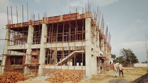


Civil Design and Drawings for Industrial Projects
Product Details:
X
Civil Design and Drawings for Industrial Projects Price And Quantity
- 1 Set
Civil Design and Drawings for Industrial Projects Trade Information
- Delivery by email
- 5 Set Per Month
- 1 Months
- Yes
- Free samples are available
- Delivery by email.
- Asia Australia North America Middle East Africa
- All India
- ISO 9001, 2015
Product Description
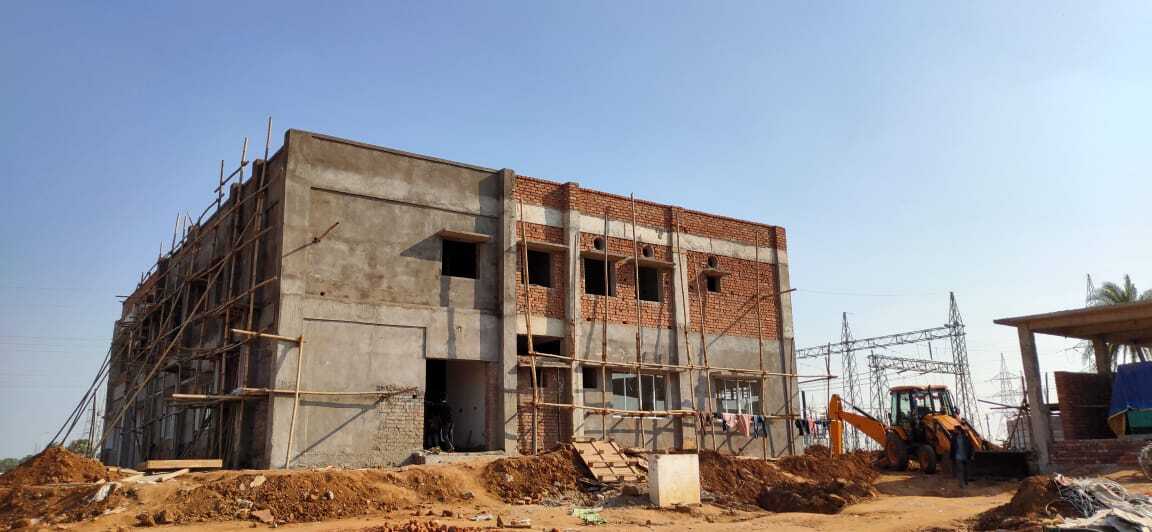
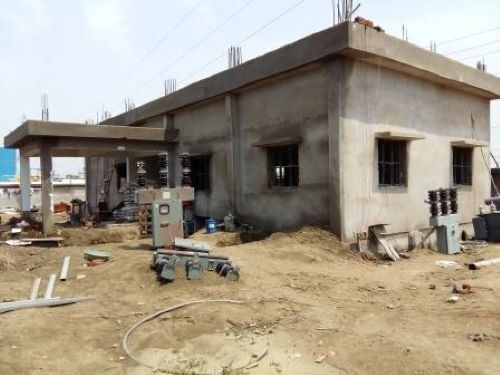
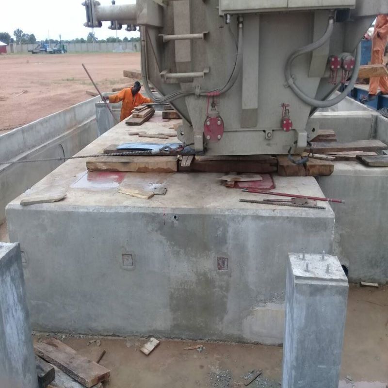
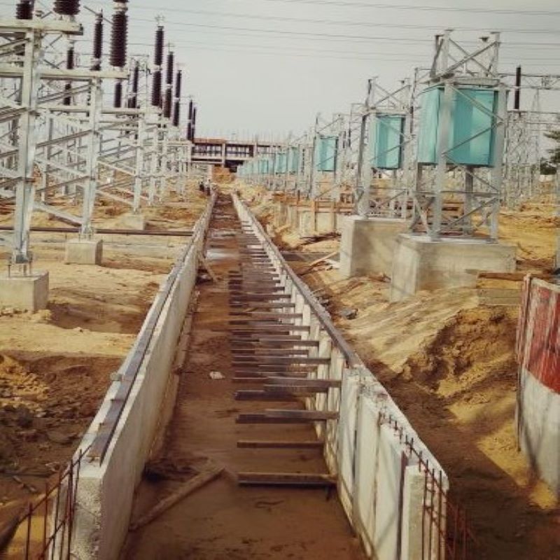
Civil Design calculation of Substation Gas Insulated Switchgear building, Control building, other Industrial buildings are required to determine the foundation size, column sizes, beam sizes, floor slab thickness, concrete grade, amount of steel reinforcement in foundation, columns, beams and floor slabs. The design is prepared on the basis of the soil characteristics, soil bearing capacity, height of the sub soil water table, dead load, live load, wind load, Seismic zone of the area where the building will be constructed.
Design of R.C.C. building is carried out in the following steps.
1. Prepare R.C.C. layout at different floor levels. In the layout, the structural arrangement and orientation of columns, layout of beams, type of slab (with its design live load) at different floor levels should be clearly mentioned.
2. Decide the imposed live load and other loads such as wind, seismic and other miscellaneous loads (where applicable) as per I.S. 875, considering the contemplated use of space, and seismic zone of the site of proposed building as per IS 1893.
3. Fix the tentative slab and beam sizes. Using the value of beam sizes fix the column section based on strong column weak beam design.
4. As far as possible, for multistoried buildings, the same column size and concrete grade should be used for at least two stories so as to avoid frequent changes in column size and concrete mix to facilitate easy and quick construction. Minimum grade of concrete to be adopted for structural members at all floors is M20 for Non Coastal Region and M30 for Coastal Region.
5. Feed the data of frame into the computer. The beam and column layouts were fixed using Autocad. Modeling was done using software STAAD Pro. connect edition. Dead loads and Live loads calculated as per IS codes and their combinations were applied on the Space frame.
6. Analyse the frame for the input data and obtain analysis output. From the analysis various load combinations were taken to obtain the maximum design loads, moments and shear on each member. All the structural components shall be designed for the worst combination of the above loads as per IS 875 Part III.
7. To design the structure for horizontal forces (due to seismic or wind forces) refer IS 1893 for seismic forces and IS 875 Part III for wind forces. All design parameters for seismic /wind analysis shall be carefully chosen. The proper selection of various parameters is a critical stage in design process.
8. The design was carried as per IS 456:2000 for the above load combinations. However, it is necessary to manually check the design especially for ductile detailing and for adopting capacity design procedures as per IS 13920.
Enter Buying Requirement Details
Contact Details
AI- 56, Ground Floor, Street no. 29, New Town, Action Area-1, Near Aahirini Market, Kolkata - 700156, West Bengal, India
Phone :08061034801
Land Line No.: 07044061210
t. 09830538398
e. satyaki.mukherjee@satcon.in
w. https://www.satcon.in/
a. AI 56, Street no. 29, New Town, Kolkata-700156, India


|
 |